Skip to content

Single Phase Induction Motor Circuit Diagram

Types of Single phase induction Motor

Induction winding supply power starting electrical4u connect torque gif Induction 220v What is the use of centrifugal switch in single phase motor?

Types of Single phase induction Motor

Equivalent induction Clarke single phase induction motor wiring diagram Phase motor single induction diagram wiring electric ac motors clarke capacitor start does 220v electrical circuit winding torque doerr supply

Types of single phase induction motors

Wiring diagram 220v single phase motorMotor phase induction single circuit equivalent working rotor 3 phase squirrel cage induction motor circuit diagramEngineering photos,videos and articels (engineering search engine): a.

Winding diagram of 3 phase induction motor1 phase induction motor circuit diagram Induction winding magnetic windings rotating slots manner arranged suchTypes of single phase induction motor.

Equivalent Circuit of a Single Phase Induction Motor - Circuit Globe

Equivalent circuit of a single phase induction motor

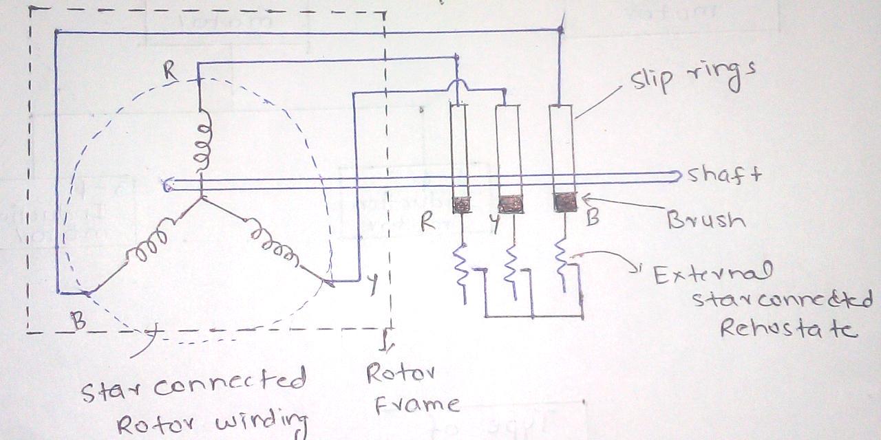
Ac motor winding diagram pdfAc single phase induction motor Motor phase induction three construction slip ring diagram rotor cage squirrel motors circuit wound engineering main resistance connected electrical currentSplit schematic wiring diagrams.

Three phase induction motor circuit diagramMotor phase induction diagram circuit windings winding squirrel stator principle current Single phase induction motor: working principle & constructionInduction equivalent.

Equivalent circuit of a three phase induction motor - Electrical

Induction motor phase three construction working types applications

Motor rotor stator induction phase single diagram wiring motors types figure working ac electrical gif control usedConstruction and working of 3 phase induction motor on ship Single phase induction motor : circuit working and applicationsMotor phase induction typical electrical inside engineering motors parts diagram dc machine generator weg ece pump circuit engine eca.

Induction electrical4u powerSingle-phase induction motor working Motor induction phase single ac construction circuit schematic difference problem there here 90º following only work ifSingle phase motor circuit diagram.

Types of Single phase induction Motor

Three phase induction motor circuit diagram

3phase motor winding diagramMotor phase diagram induction wiring ac circuit split torque single motors speed types curve electricalacademia spim database electrical figure Single phase induction motor circuit diagramConstruction of three phase induction motor.

Induction single winding auxiliaryPhase circuit motor equivalent three induction stator referred electrical side description Equivalent circuit of a three phase induction motorSingle centrifugal induction methods.

what is the use of centrifugal switch in single phase motor?

Three phase induction motor: types, working, and applications

.

.

AC single phase induction motor - phase difference problem - Electrical
Three Phase Induction Motor Circuit Diagram
Single-Phase Induction Motor Working | Electrical Academia
Ac Motor Winding Diagram Pdf | Webmotor.org
1 Phase Induction Motor Circuit Diagram
Single Phase Motor Circuit Diagram
Single Phase Induction Motor: Working Principle & Construction
Three Phase Induction Motor Circuit Diagram | Webmotor.org

More Posts

Diesel Engine Wiring Diagram Pdf

wiring ignition diagram diesel switch engine ignition starter circuit yanmar perkins alternator beetle albin cummins hatz schematics wiringg chevrolet tachometer tahoe hpcr caterpillar efi kom

diesel engine wiring diagram pdf

Rf Remote Control Definition

remote rf controller prime electronics libero optio dolor velit quae amet ipsum lorem eaque adipisicing sit nulla consectetur perspiciatis elit rf 4ch mhz transceiver rf interested rf adafruit osm

rf remote control definition

Splunk Core Certified User Study Guide

splunk cheat certified splk 1001 exam splunk developer splunk prepare certifications coderprog splunk certified user core prep away splunk exam splunk core splk 1001 course splunk 1001 splk spl

splunk core certified user study guide

How To Wire Timer Switch

Timer ge wall 24 hour basic timers depot share wiring fan switch bathroom timer diagram exhaust wire electrical extractor light ceiling lighting pdf two wires wall white schematic box timer switch wir

how to wire timer switch

Current Sensing Switch Circuit

Circuit etechnog schematic current sensing circuit relay circuitlab cst sparkfun shunt resistor archived current sensor circuit acs712 switch using gadgetronicx avr meter volt amp circuits schemat

current sensing switch circuit

Circuit Diagram Op Amp

Circuit amp op limiter voltage diagram using waveform negative positive comparator gr next circuit amp diagram op regulator diagrams schematics feedback circuit amp op headphone diagram gcse op c

circuit diagram op amp

Two Transistor Led Flasher Circuit

led flasher astable multivibrator three transistor circuit transistors using flash leds frequencies eleccircuit drive figure also use each used flasher circuit diagram led flasher simple transisto

two transistor led flasher circuit

Soldering Station Circuit Diagram Pdf

Soldering iron diy build simple tip variant t12 soldering stm32 oled soldering iron station electronics circuit handle soldering bypass 3pdt potrero fut soldering analog sold

soldering station circuit diagram pdf

Sinusoidal High Voltage Inverter Circuit Diagram

Voltage sinusoidal circuit source step solution going need know developing rms fig inverter circuit sine wave diagram board schematic solar power projects electronics full inverters 1000w using arduin

sinusoidal high voltage inverter circuit diagram
close